1
/
of
1
Electronic City المدينة الالكترونية
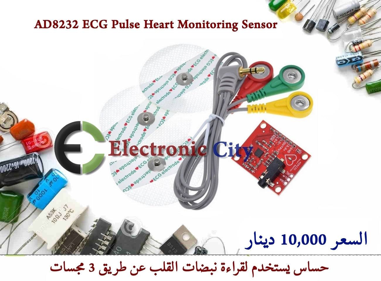
ECG Monitoring Sensor AD8232 Heart monitor #S2 012018
ECG Monitoring Sensor AD8232 Heart monitor #S2 012018
Regular price
10,000 IQD
Regular price
Sale price
10,000 IQD
Unit price
/
per
Couldn't load pickup availability
ECG Monitering Sensor
حساس تخطيط القلب ECG
حساس يستخدم لقراءة نبضات القلب عن طريق 3 مجسات وارسال البيانات الى المتحكمات مثل الاردوينو
يتوفر بسعر 10,000 دينار
Application
Fitness and exercise heart rate monitoring
Portable ECG
Remote health care
Gaming peripherals
Biological signal acquisition
Pin No. Name Description
1 HPDRIVE Qualcomm drive output. HPDRIVE should be connected to the first high-pass filter capacitor.
AD8232 drive the pin to keep HPSENSE with the reference voltage at the same level.
2 + IN instrumentation amplifier positive input. + IN is usually connected to the left arm (LA) electrode.
3 -IN negative input of the instrumentation amplifier. -IN Is usually connected to the right arm (RA) electrodes.
4 RLDFB right leg drive feedback input. RLDFB is the feedback pin right leg drive circuit.
5 RLD right leg drive output. Should drive electrode (usually the right leg) to connect the pin to the RLD.
6 SW fast recovery switch pin. The pin should be connected to the output of the second high-pass filter.
7 OPAMP + op-amp input.
8 REFOUT reference buffer output. Instrumentation amplifier output reference to this potential.
REFOUT should be used as a circuit at any point in the reference signal requires a virtual ground.
9 OPAMP- inverting input terminal of the operational amplifier.
10 OUT of the operational amplifier output. This output providing a fully conditioned heart rate signal.
OUT can be connected to the input of the ADC.
11 LOD- lead off the comparator output. DC lead-off detection mode, when disconnected from the -IN electrode,
LOD- in a high state, and vice versa in a low state. In exchange lead-off detection mode, LOD- always in a low state.
Lead-off of the comparator output. DC lead-off detection mode, when the + IN electrode is disconnected, LOD + in the high state,
And vice versa in the low state. In exchange leads off detection mode, when -IN or + IN electrode is disconnected, LOD + in the high state,
Is at the low state when the two electrodes are connected.
12 LOD +
13 SDN shutdown control input. The SDN driven low, you can enter a low-power shutdown mode.
14 AC / DC lead-off mode control input. For DC lead-off mode, should AC / DC pin is driven low.
For AC lead-off mode, should AC / DC pin is driven high.
15 FR quickly regain control input. The FR driven high enables fast recovery mode; otherwise, it should be driven low.
16 GND Power Ground.
17 + VS supply pin.
18 REFIN reference buffer input. REFIN (high-impedance input pins) can be used to set the reference voltage buffer level.
19 IAOUT instrumentation amplifier output pin.
Qualcomm detection input 20 HPSENSE instrumentation amplifier.
HPSENSE should be connected to the R and C to set the blocking circuit node transition frequency.
EP exposed pad. Exposed pad should be connected to GND or unconnected.
Materials
Materials
Shipping & Returns
Shipping & Returns
Dimensions
Dimensions
Care Instructions
Care Instructions
Share